


EXAMPLE TEST
SYSTEMS
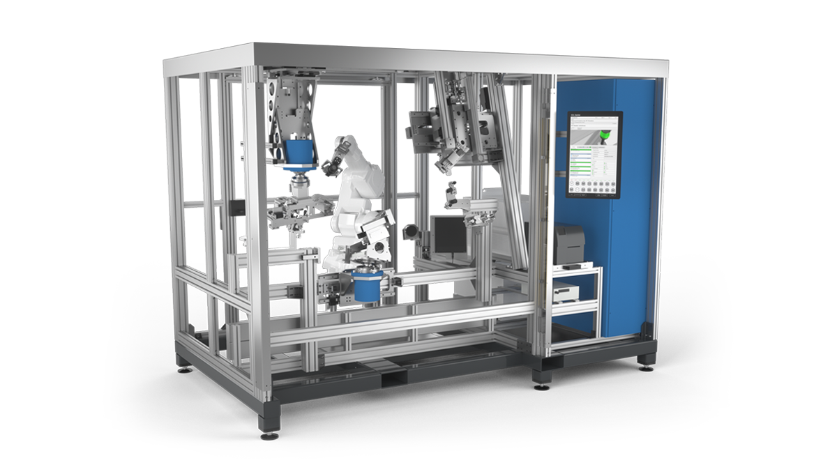
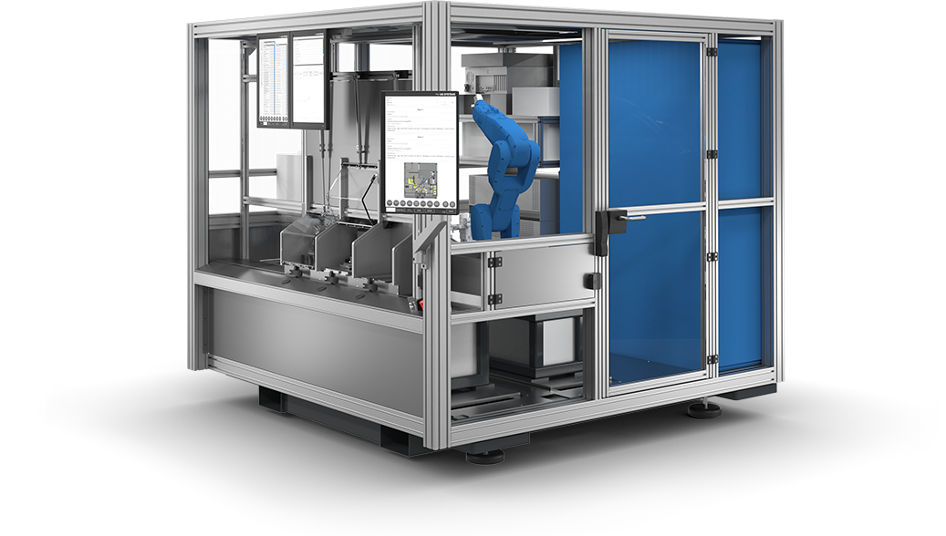
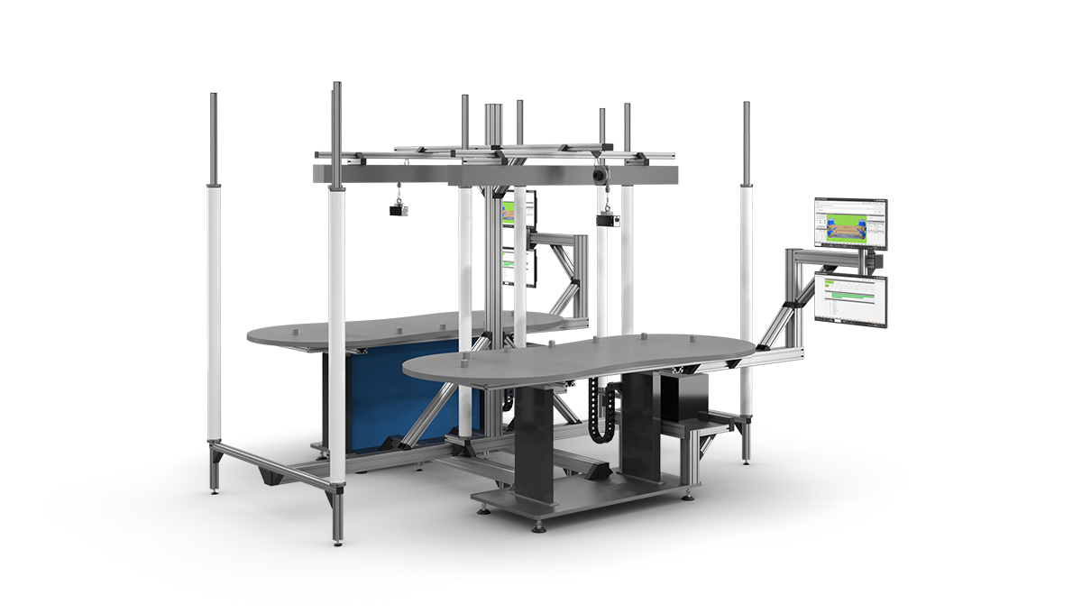
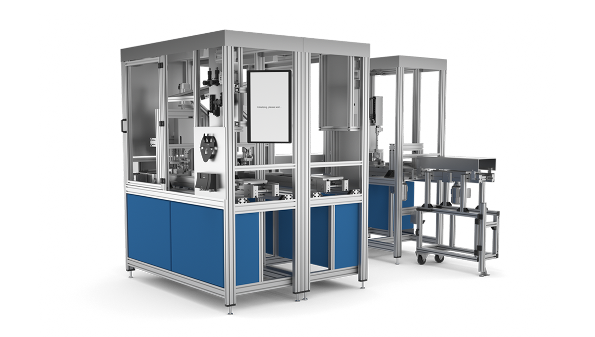
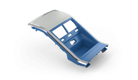
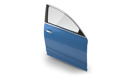
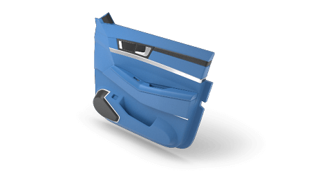
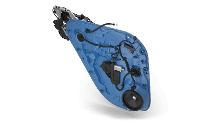
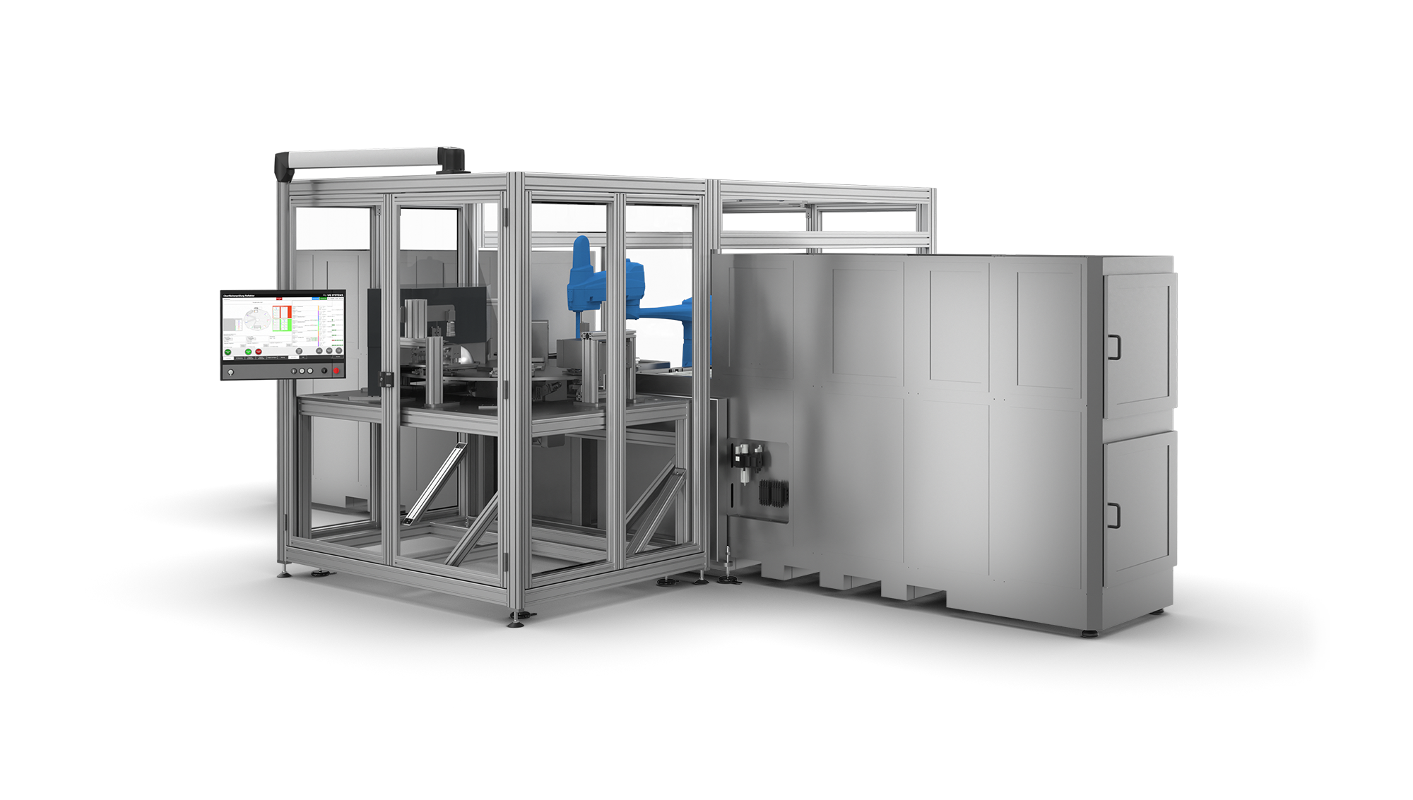
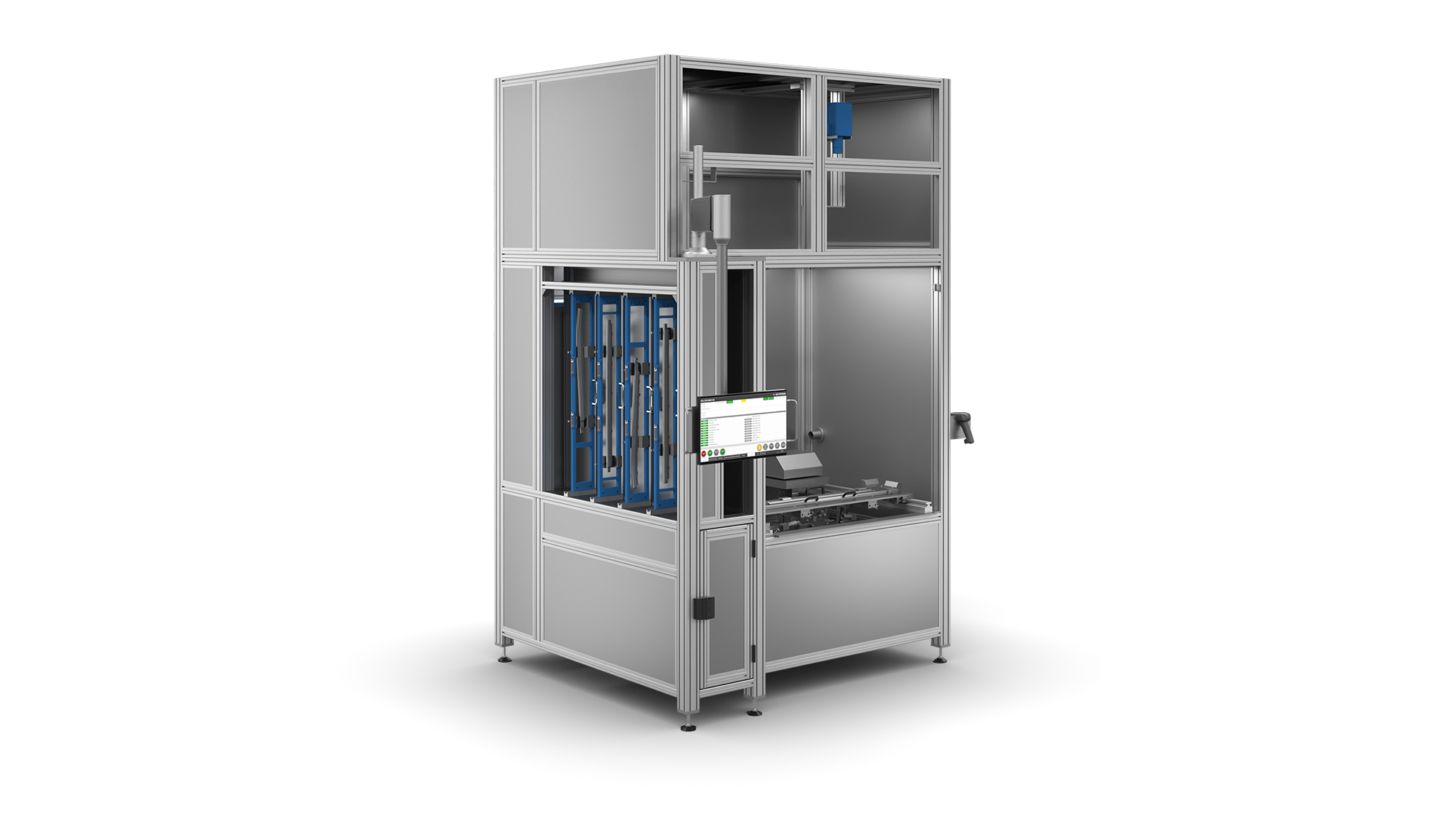
Robot-based door module test system
- Testing of all door module components (window regulator, lock, speakers, KG antenna, crash sensor, etc.)
- Universal, automatically adjusting receptacle for different door module variants
- Robots for variant changeovers and camera-based tests
- 3D positioning systems for individual receptacle assemblies
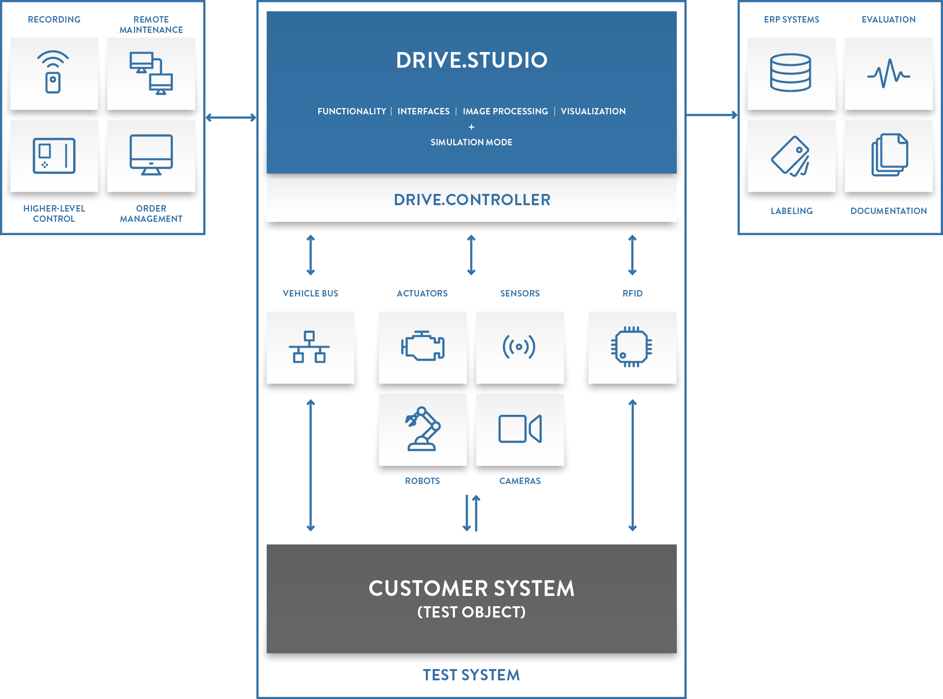
- Image processing integrated into the control software (online/offline configuration)
- Communication with LIN/CAN control units
- Control of the robot and multiple servo drives via the PC system software
- Connection to order control system
- Labeling of the door module
- Documentation of the test results, incl. photos
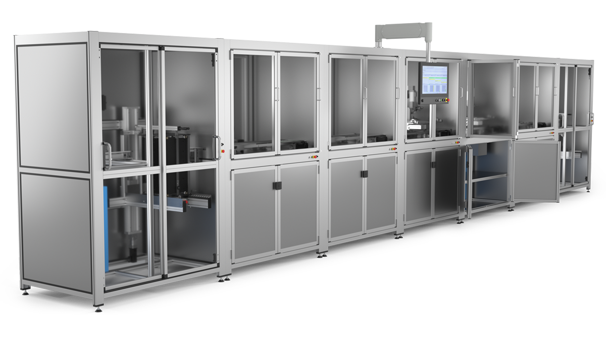
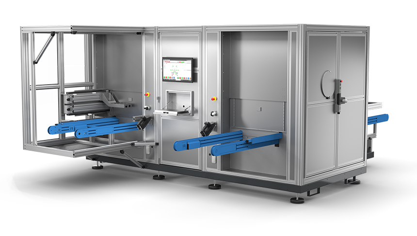
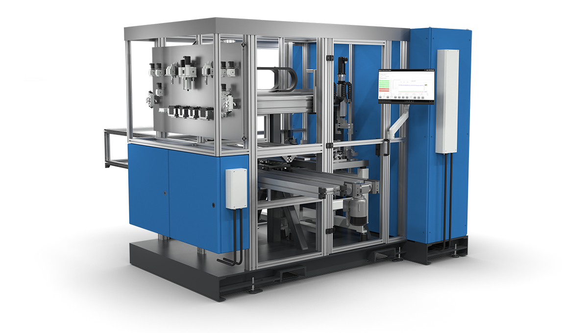
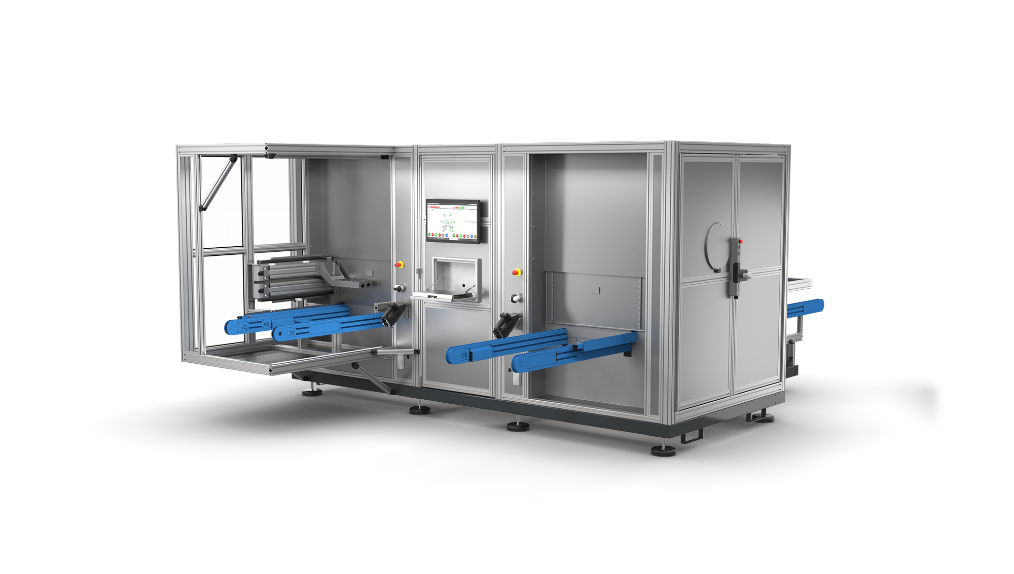
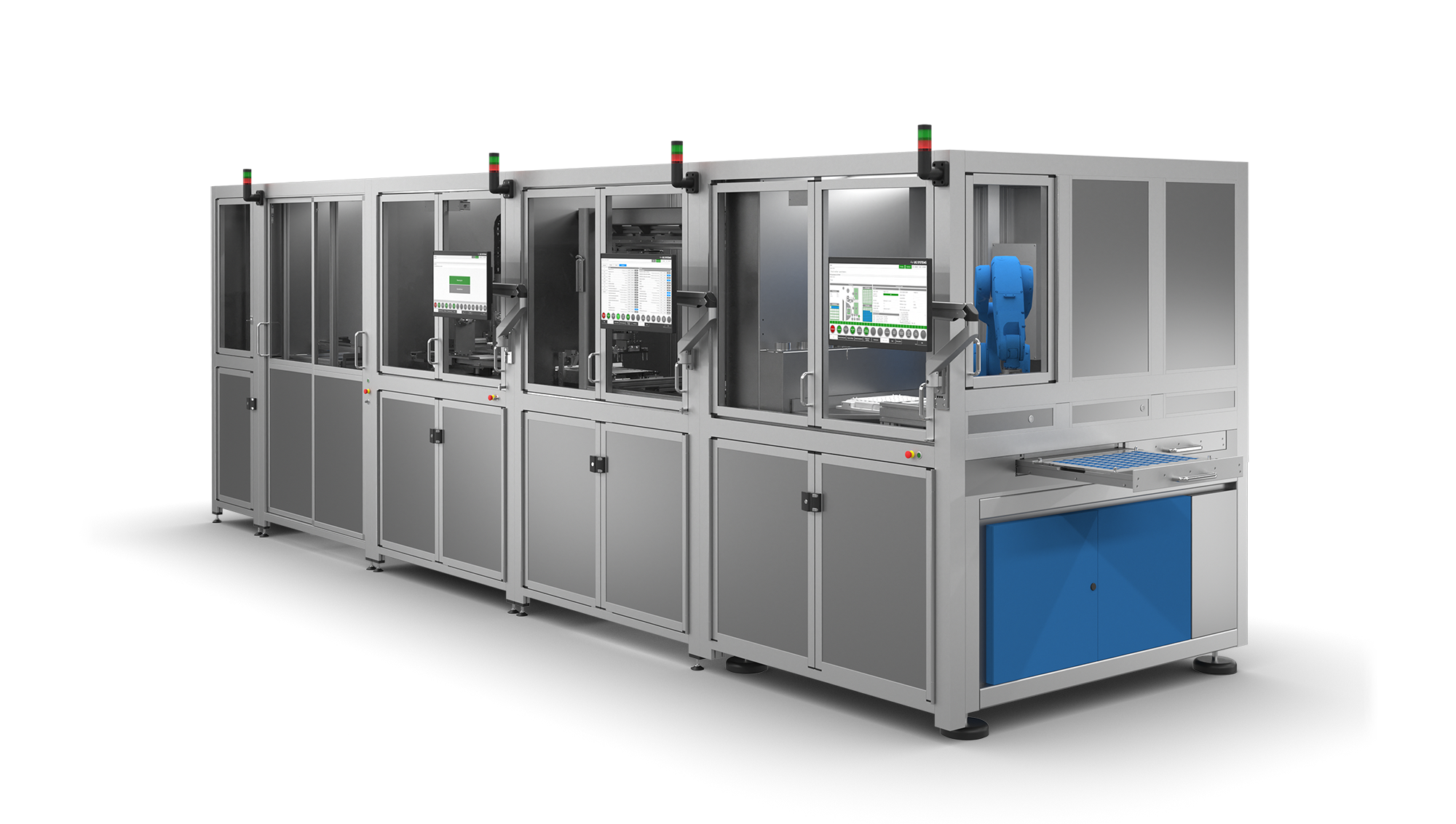
LED module test/parameterization/
calibration system
- Use of different module ICs (Melexis, Elmos, etc.)
- 5 processing stations, panel loader, panel unloader
- Automatic feeding of panels from the magazine
- Flashing of module software
- Serial number allocation (unique across multiple systems)
- IC function tests (auto-addressing, temperature sensor, etc.)
- Burning-in (up to approx. 60 seconds)
- Spectrometer measurement of the color and brightness of the color chips
- Calculation of parameters for calibration and writing to IC
- Control of 26 servo drives, 8 LIN channels, 2 spectrometers, etc.
- Cycle time per module ‹ 2 seconds
- Documentation of all module data
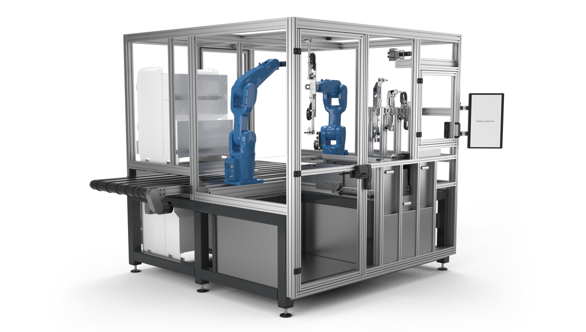
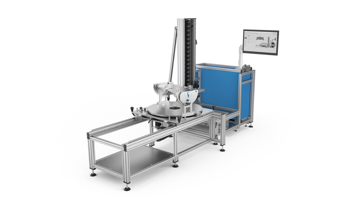
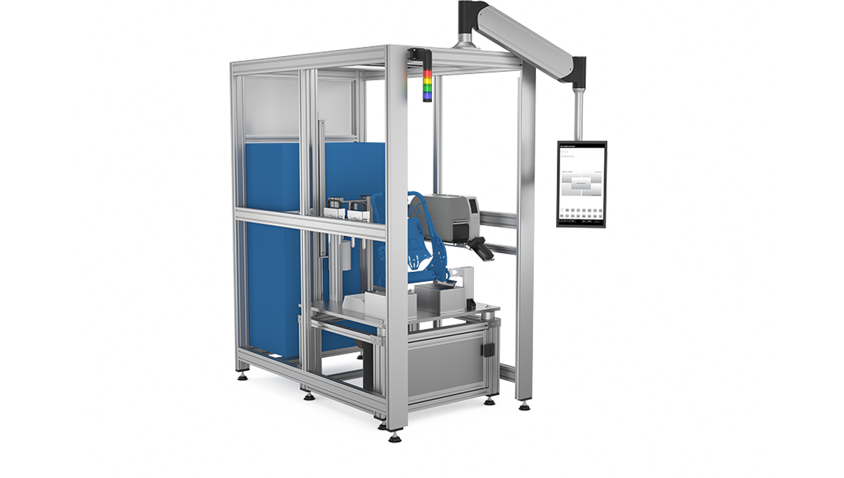
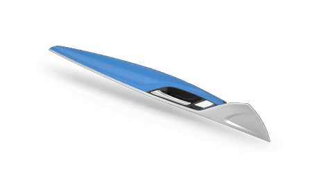
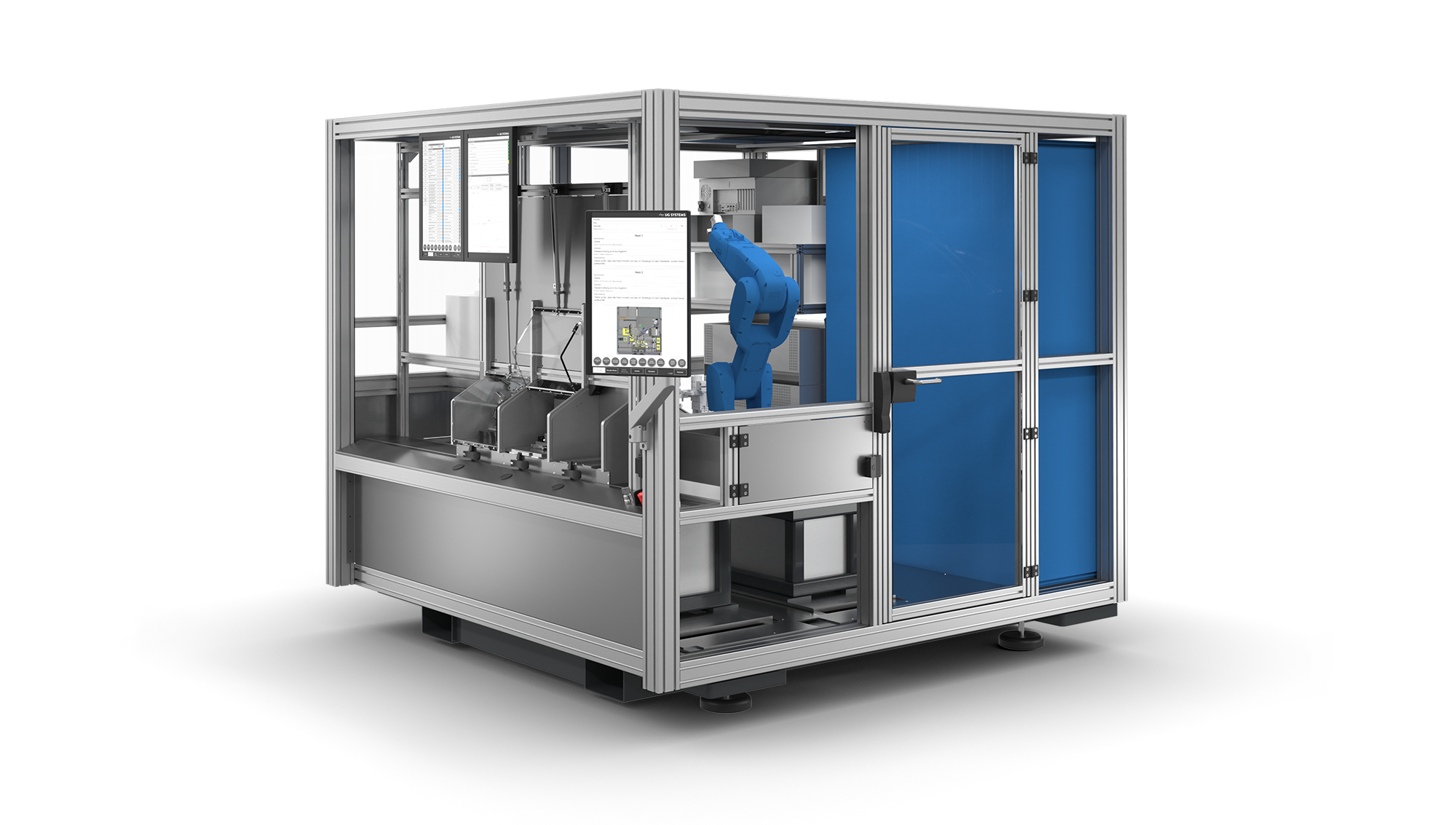
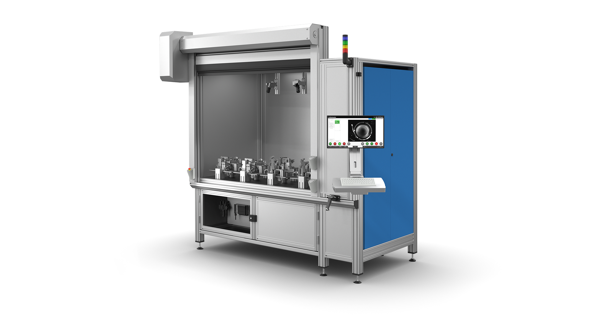
Robot-based
UNI light test system
- Lighting evaluation of light conductors and assembly components
- Automatic adjustment of the robot gripper for different test object variants
- Manual feeding or direct connection to injection molding process
- Test objects are identified on an infeed conveyor and their position is determined
- Gripping and positioning (LED or contacting by the first robot)
- Image recording by camera on the second robot
- Wide variety of evaluation methods
- Marking of the light conductor or assembly component
- Sorting and depositing in customer-specific packaging
- Documentation of the test results, incl. photos

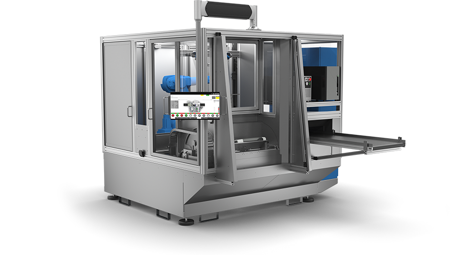
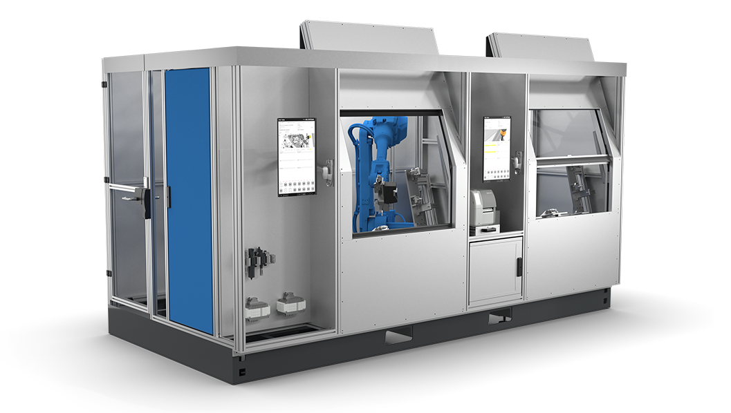
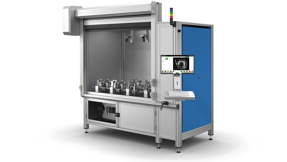
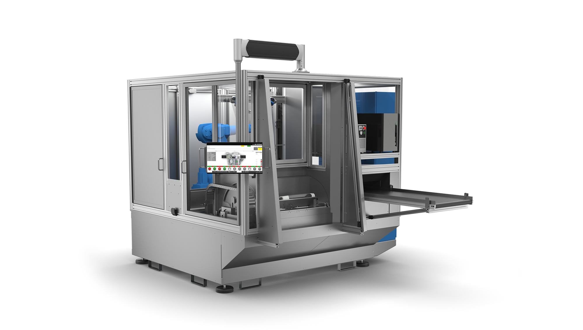
Surface test system
- Fast and efficient testing of components with different surfaces (painted, chrome-plated, coated)
- Different methods for image acquisition (shape-from-shading, deflectometry, etc.)
- Precise and accurate analysis results for the evaluation of quality and condition of surfaces for the process-safe detection of defects or irregularities, among others through the use of artificial intelligence
- Image processing integrated into the control software (online/offline configuration)
- Feeding via trays in several tray stacks (high autonomy time)
- Handling of components by SCARA robot
- Tests are carried out along a round-cycle table
- Sorting and depositing in trays (tray stacks)
- Adaptation to different component sizes and shapes
- Documentation of the test results
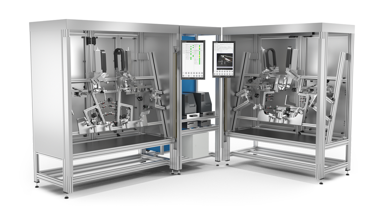
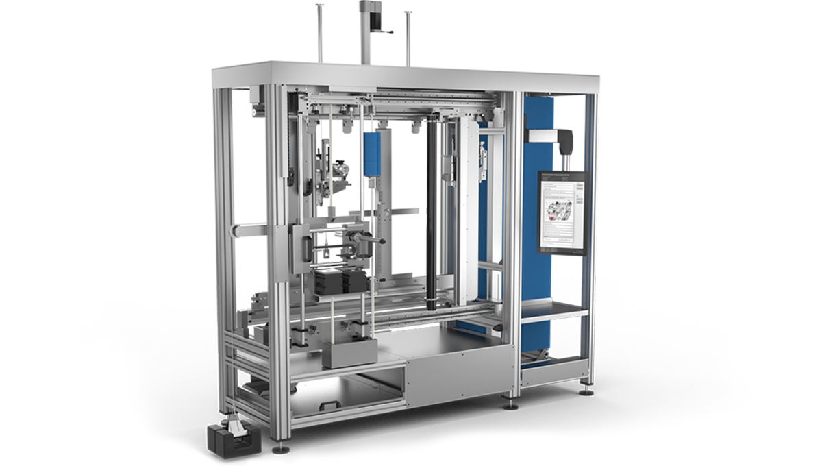
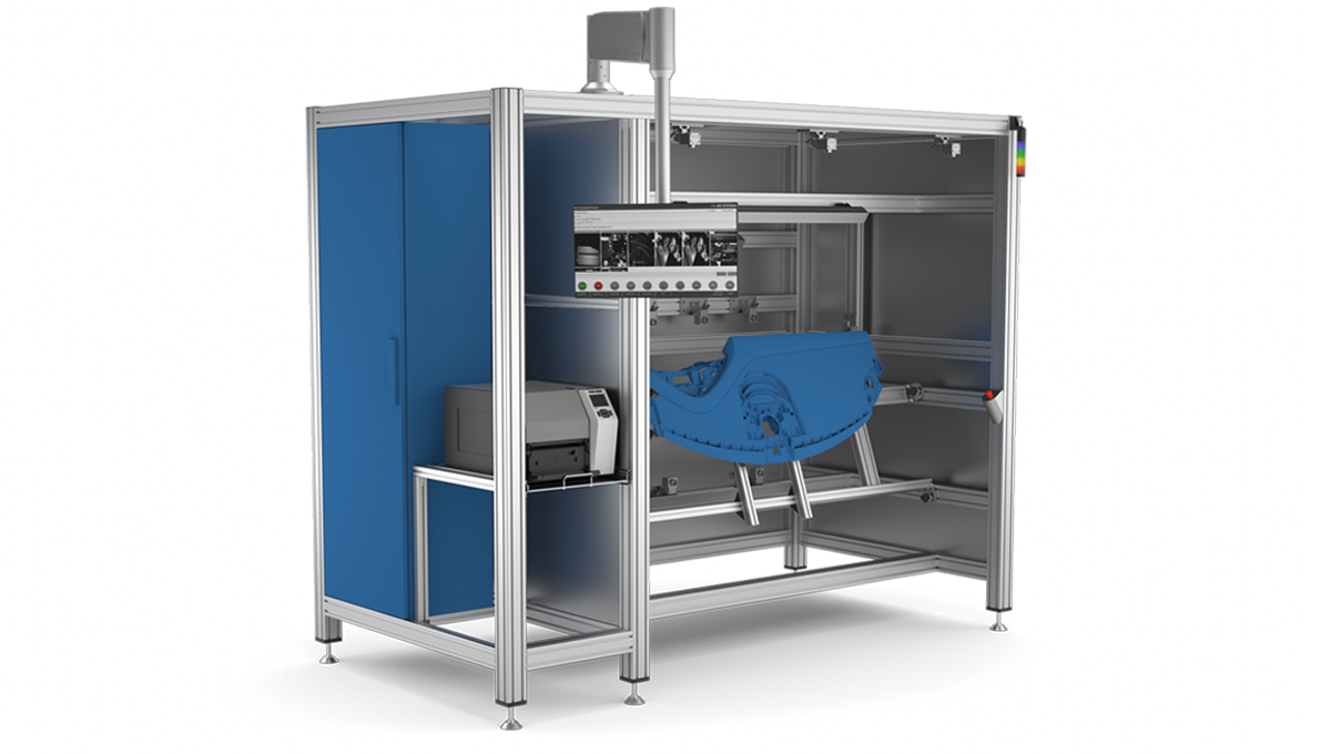
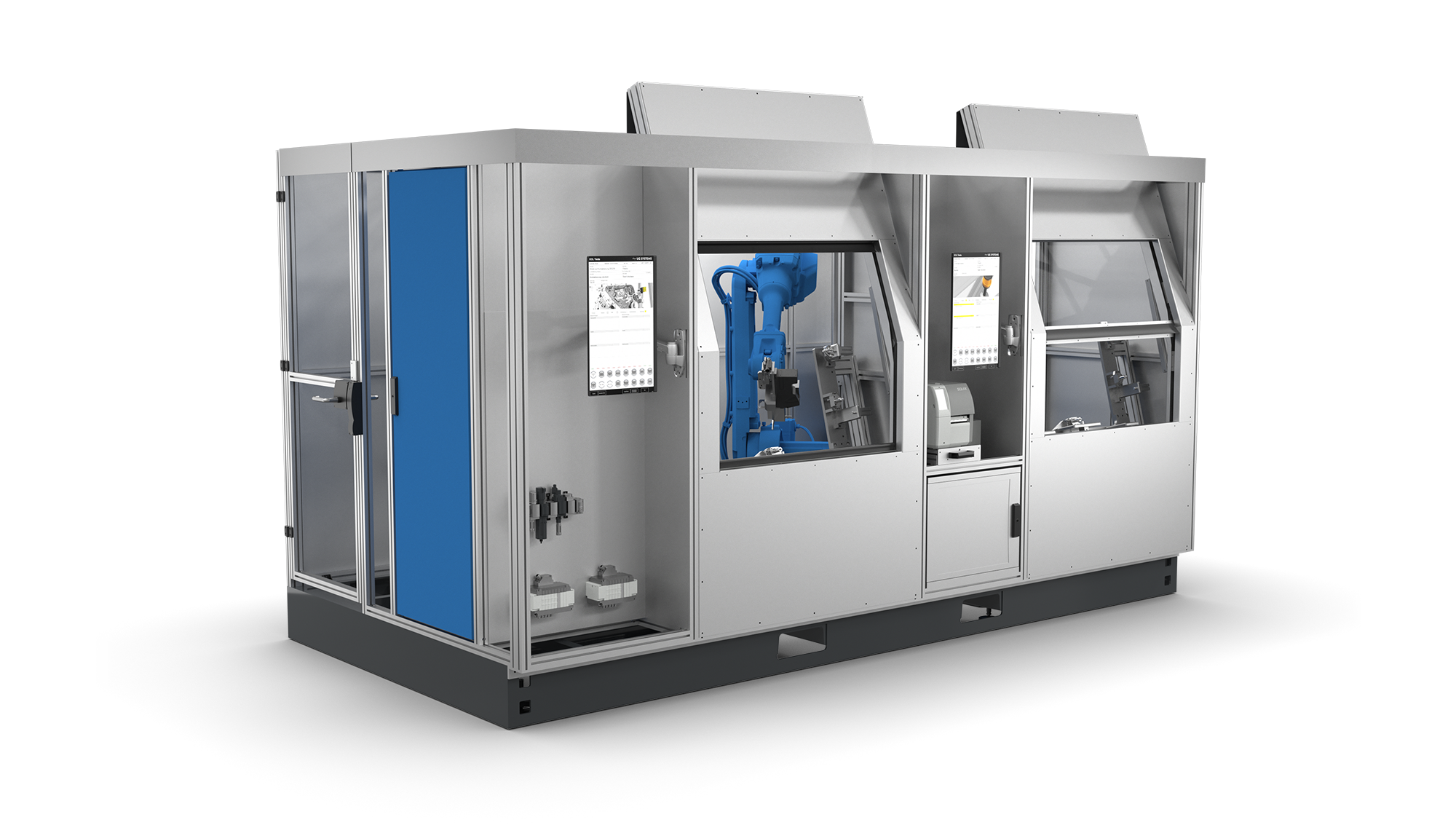
Robot-based
light test system
- End-of-line test of light components for a homogeneous appearance in the vehicle
- Evaluation of direct and indirect light
- Test of components without LED modules (light is coupled in the system) and with LED modules or LIN LED modules
- Cycle time optimization through vertically rotating rotary indexing table
- Part handling robot: Picking from receptacle, positioning for pin test, positioning for laser marking, sorting or depositing on conveyor belt
- 3D printed parts to simulate the radiating surfaces of the vehicle (simulation of the installation environment)
- Reading out and checking of LIN LED module data (type, version, serial number, status, error information, etc.)
- Specially developed evaluation methods for optimal analysis
- Graphic representation of the measurement data
- Generation of reports about individual test objects, selectable time periods, statistical evaluations, etc.
- Exchange parts for multiple variants
- Presence check of various attachment parts
- Automatic adjustment of the robot gripper
- Pin test (wobble circle test)
- Laser marking
- Sorting and depositing on conveyor belt
- Documentation of the test results, incl. photos

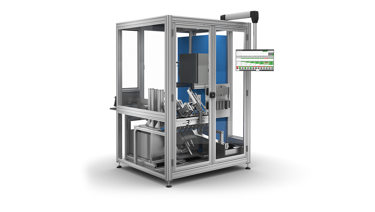
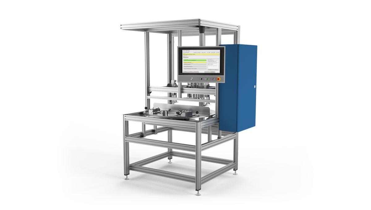
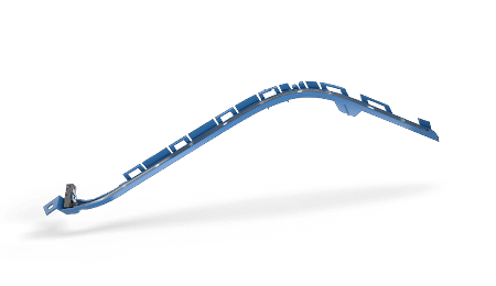
Seat rail test system
- Crack testing on seat rails immediately after the stamping process
- Automatic changeover for different variants (incl. feed-through mode)
- 3D measurement and evaluation of cracks
- Recording of bending radii using nine 2D profile laser systems
- Image processing and image evaluation in 120 ms
- OK/NOK sorting, incl. documentation
- Processing time per seat rail ‹ 1.3 seconds
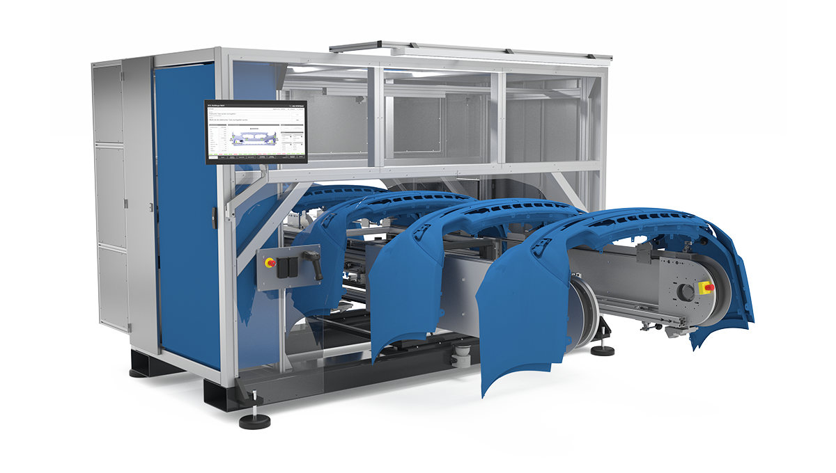
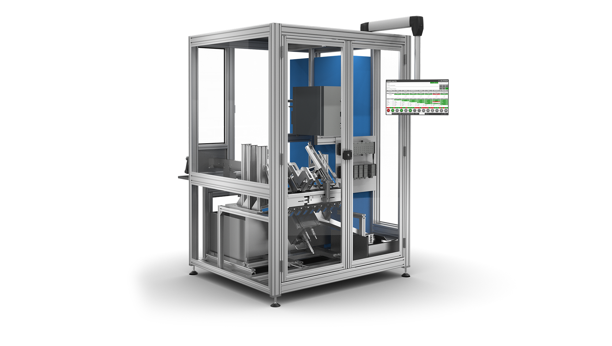
Door panel
test system incl. electronics
and light testing
- Camera-based variant matching of installed components (design, color, etc.)
- Presence check of various attachment parts
- Surface inspection (scratches, defects, etc.)
- Electrical key test (LIN communication, resistance measurement)
- Evaluation of direct and indirect light (homogeneity)
- Buffer conveyor system without safety devices
- Flexible component receptacle
- Labeling
- Connection to order control system
- Photo documentation
- Documentation of the test results, incl. photos

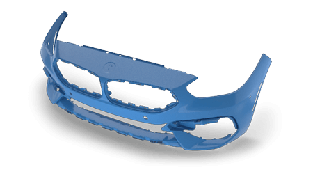
Bumper test system
(random check)
- Test object receptacle for different variants
- Reflection and transmission measurement (measurement technology from Rohde & Schwarz)
- Four-dimensional axis system for positioning of measuring fields
- In-system calibration of the measuring system
- Documentation of the test results
Robot-based door module test system
(3D measurement technology)
- Testing of all door module components (window regulator, lock, speakers, KG antenna, crash sensor, etc.)
- 3D images by robot-guided 2D line scanner
- Measurement and evaluation of test characteristics using 3D image processing
- Image processing integrated into the control software (online/offline configuration)
- Communication with LIN/CAN control units
- Control of the robot via the PC system software
- Connection to order control system
- Labeling of the door module
- Documentation of the test results, incl. photos and measurements
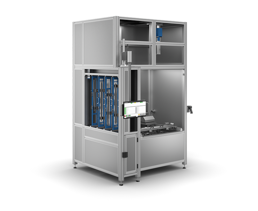
Interior lighting test system
(luminance camera)
- Series test of lighting components for a homogeneous appearance in the vehicle
- Direct light measurement by means of luminance camera
- Testing components with ISELEDs
- Reading out and checking the LED data (type, version, status, error information, etc.)
- Specially developed evaluation methods for optimal analysis
- Graphic representation of the measurement data
- Generation of reports about individual test objects, selectable time periods, statistical evaluations, etc.
- Exchangeable disk system for multiple variants
- Presence check of various attachment parts
- Laser marking
- Documentation of the test results, incl. photos

LED module test/parameterization//
calibration system (multi-side LED module)
- 3 processing stations, panel loader, module storage in trays
- Automatic feeding of panels from the magazine
- Use of different module ICs (Melexis, Elmos, etc.)
- Flashing of module software
- Serial number allocation (unique across multiple systems)
- IC function tests (auto-addressing, temperature sensor, etc.)
- Burning-in (up to approx. 60 seconds)
- Depaneling by milling
- Module handling by robot
- Spectrometer measurement of the color and brightness of the color chips
- Calculation of parameters for calibration and writing to IC
- Control of servo drives, LIN channels, spectrometers, etc.
- Cycle time per module ‹ 1 seconds
- Documentation of all module data
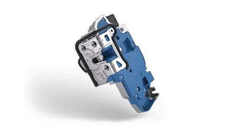
Door module test system
- Series test of all door module components (window regulator, lock, speakers, KG antenna, crash sensor, etc.)
- Two door modules can be tested in parallel in two receptacles
- Communication with LIN/CAN control units
- Reading out and checking of control unit data (type, version, serial number, status, error information, etc.)
- Multiple vision sensors for installation tests
- Connection to order control system
- Labeling of the door module
- Documentation of the test results, incl. photos
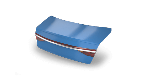
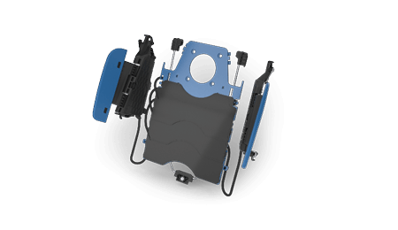
Tailgate test system
- Endurance test of mechanical and electric tailgates
- Damage-free adaption of the tailgate using vacuum
- Direct testing of the complete tailgate on the vehicle possible
- Testing of individual tailgate components using dummy structure
- Two climate-proof servo drives
- Servo‐controlled learnable movement curve
- Actuation of the tailgate up to a speed of 2 m/s
- Force and angle measurement
- Tests performed at ‐40 °C to +85 °C
- Remote control with emergency stop function
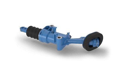
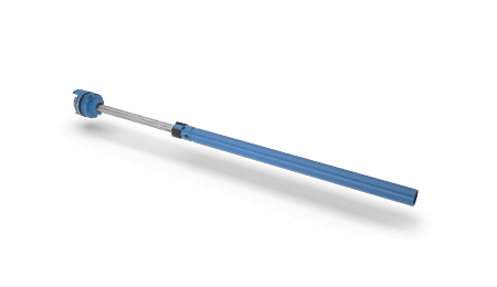
Robot-based clutch master
teach-in test system
- Parallel processing of several clutch masters
- Linearization of the measurement curve and storage of parameters in the electronics of the clutch master
- Precise positioning
- Automatic fixing and contacting
- Reading out and checking of clutch master data (type, version, serial number, status, error information, etc.)
- Dynamic load application
- High-precision measurement to record the actuating travel
- Real-time control system (NI cRIO, Bosch Rexroth drives)
- Leak test
- Establishing the delivery position
- Laser labeling
- Control of the robot via the PC system software
- Graphic representation of the measurement data
- Documentation of the test results
LED module test system
- Cycle-independent feeding
- Parameterization/verification of module data
- LIN communication
- Spectrometer measurement with testing of color and brightness
- Wobble circle test of the pins
- Laser marking
- Reading out the laser marking, e.g. by means of OCR
- Cycle time per module ‹ 2 seconds
- Documentation of all module data
Interior lighting test system
- Series test of lighting components for a homogeneous appearance in the vehicle
- Evaluation of direct and indirect light
- Test of components without LED modules (light is coupled in the system) and with LED modules or LIN LED modules
- 3D printed parts to simulate the radiating surfaces of the vehicle (simulation of the installation environment)
- Reading out and checking of LIN LED module data (type, version, serial number, status, error information, etc.)
- Specially developed evaluation methods for optimal analysis
- Graphic representation of the measurement data
- Generation of reports about individual test objects, selectable time periods, statistical evaluations, etc.
- Exchangeable disk system for multiple variants
- Presence check of various attachment parts
- Labeling of the lighting components
- Documentation of the test results, incl. photos
Bumper test system
- Optical presence test for integrated components (sensors, clips, …)
- Safe DUT jig for different variants
- Automatical transport
- Automatical surface inspection
- Automatical photo documentation
- Type/variant identification via RFID
- Documentation of the test results
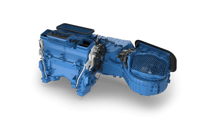
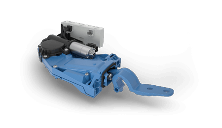
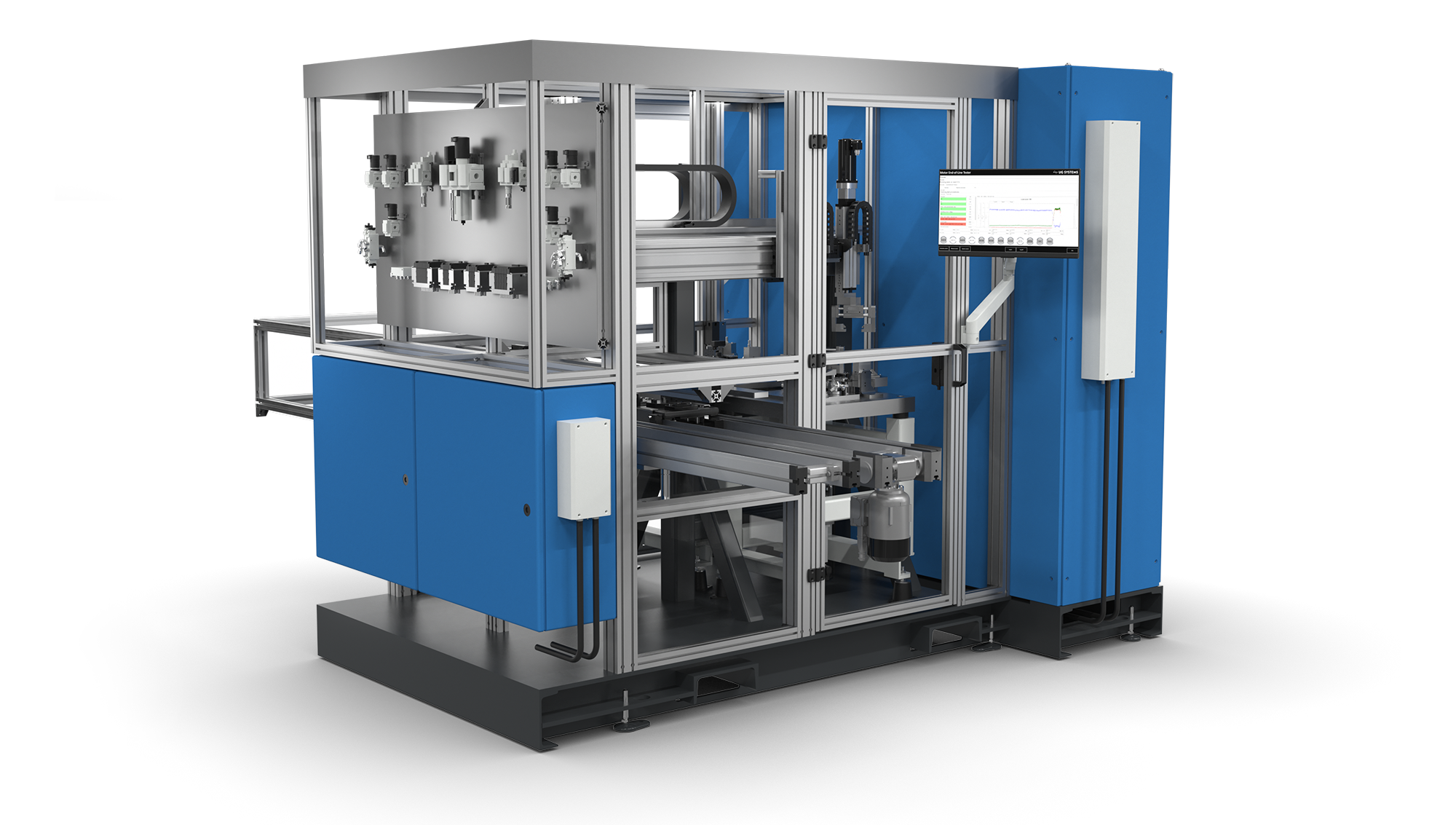
Motor test system
- End-of-line test integrated into assembly line
- Test of load points, current curve, acoustics, etc.
- Dynamic load application
- Real-time control system and measurement technology through NI components (cRIO)
- Activation via LIN
- Connection to order control system
- Gantry system with double gripper for the handling between test object receptacle and workpiece carrier system
- Optional inline flashing of bootloader and application software
- Documentation of the test results
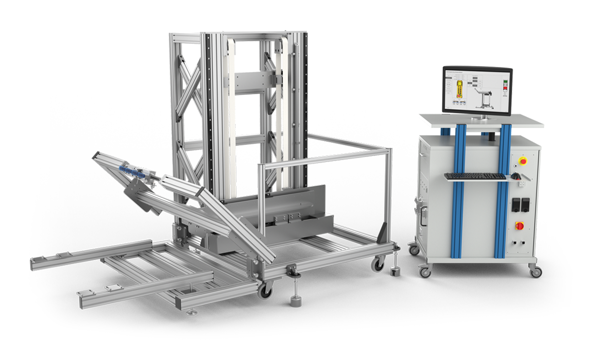
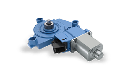
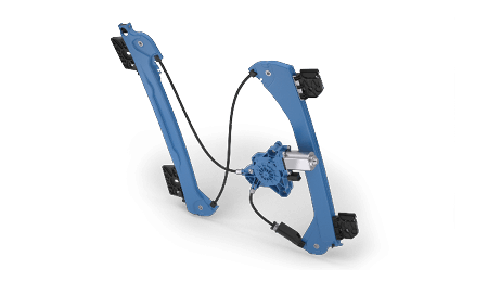
UNI window regulator/door module test system
- Tests on different window regulator and door module variants during series production
- Programmable real-time control for position-dependent window regulator load (electrical weight, NI cRIO)
- Control via LIN and CAN (CANoe remaining bus simulation)
- Servo drive for moving manual window regulators
- Fast measurement technology via NI DAQ
- Force measurement by means of window regulator stroke
- Laser measurement for form testing
- Programmable button control (resistance‐coded, time‐coded)
- Universal receptacle thanks to manually adjustable receptacles for different window regulator/door module variants
- Documentation of test results,
- Generation of test/measurement log (PDF)
UNI lock test system
- Tests for different lock variants during series production
- Intuitive and reproducible positioning of the receptacle (x, y, z, incline)
- Servo drive for positioning the load/measuring unit
- Control via time-coded outputs or LIN
- Servo drive pressure and tension measurement
- Force measurement
- Fast measurement technology through NI components
- Manually adjustable variant-specific receptacles
- Individually configurable test sequences
- Documentation of test results,
- Generation of test/measurement log (PDF)
Bumper test system
- Testing of all electrical components on a bumper (parking sensors, radar sensors, lights, etc.)
- Testing of parking sensors by means of distance measurement
- Position detection on cable harness
- Reading out and checking of component data (type, version, serial number, status, error information, etc.)
- Object receptacle adjustable in height for different variants
- Optional photo documentation
- Type/variant identification via RFID
- Documentation of the test results
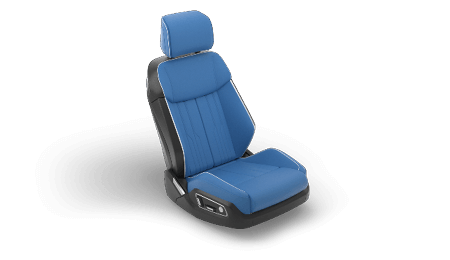
Seat backrest test system
- Structure-borne sound and electrical function test of the metal structure
- Head rest adapter/simulation
- Weight simulation with weights or motor
- Automatic positioning of the acceleration sensors
- Environment decoupling
- Sound analysis
- PWM motor control
- PLC/PC controlled
- Labelling and documentation of test results
Seat comfort test system
- Function tests for pneumatic seat comfort modules (lordosis, lateral support, massage, etc.)
- Load application on the individual air cushions
- Path and time measurement for the aeration and ventilation of individual air cushions
- High-precision pressure measurement
- Pump simulation
- Communication to the control unit via LIN/CAN/CANoe remaining bus simulation
- Reading out and checking of control unit data (type, version, serial number, status, error information, etc.)
- Exchangeable receptacles for different module variants
- Labeling of the seat comfort module
- Documentation of the test results
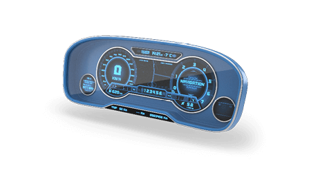
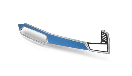
Dashboard test system
- Presence check of all attachment parts on the dashboard
- 8 industrial cameras for testing 25 characteristics
- Infrared lighting for independence from daylight
- Connection to order control system
- Labeling of the dashboards
- Documentation of the test results, incl. photos
Motor actuator test system
- Series tests integrated into assembly line
- Bosch transport system, incl. branches to various test systems
- Automatic contacting and pinion adjustment
- Reading out and checking of actuator data (type, version, serial number, status, error information, etc.)
- Dynamic load control
- Leak test
- Establishing the delivery position
- Automatic labeling of the actuator
- Automatic removal of NOK tested actuators
- Documentation of the test results


